REGULATED POWER SUPPLY
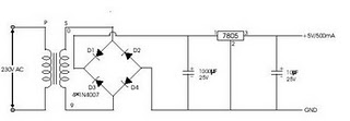
Circuit diagram for 5V supply
In this circuit, we use a step down transformer having the capacity of 500mA which converts 220V AC to 9V AC. After it we use bridge rectifier circuit which converts 9V AC to 9V DC. Now we can see that IC 7805 is used. this IC is used to convert 9V to exactly 5V. This is a fixed voltage regulator IC. IN4007 diodes are used in bridge rectifier circuit.
The first capacitor is used to minimize repples and to have smooth DC supply. It is an electrolytic capacitor of 1000uF. The second capacitor of value 103pF is used for filter and to eliminate the voltage oscillations at the output due to large voltage oscillation at the input of regulator.
The fixed voltage regulator IC has 2.5V voltage drop across itself.ICs for different power supplies.
For 12 V use IC 7812
For 9V use IC 7809
For 5V use IC 7805
As I told you that these ICs have 2.5 V voltage drop across itself. So always use transformer which give you aleast 2.5 V extra voltage, hence you will get desired voltage.
About IC LM317
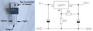
The circuit diagram is shown below.
Component List:
R1- 270 ohm
R2- 2K
C1=C2 - 103 pF ( Ceremic Capicitor)
IC -LM 317
As you can see that IC has three pins. First pin is input pin and last pin is output pin. Middle pin is grounded
but a potentiometer is connencted in series.
By adjusting potentiometer, you can have desired voltage.


